

How Does Uniform Feeding Improve Twin Screw Extruder Output in Powder Coating?
How Does Uniform Feeding Improve Twin Screw Extruder Output in Powder Coating?
Is your twin screw extruder possibly sized to meet your required production, but is it running irregularly? Check the feed to the extruder prior to making any alterations to screw speed. Bridging, erratic dosing and poorly mixed premix can all affect the machines’ ability to work at its full potential and result in it operating below its actual capacity. Uniform feed to the screws allows them to work consistently with material in conveyance, kneading, dispersion, cooling and discharge between each section in turn.
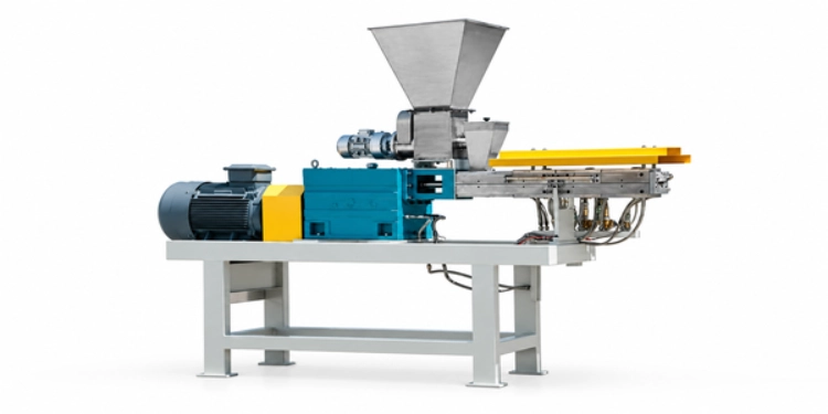
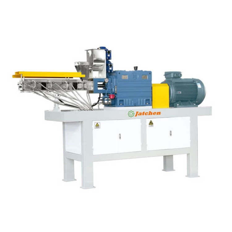
TSK TWIN SCREW EXTRUDER supplied by Yantai Jatchen Powder Coating Processing Equipment Co., Ltd. includes anti-bridge screw feeding, uniform feeding, deep-groove low-shear screw, multi-zone control and PLC/HMI program control. For best results this unit must be fed with a prepared premix and be supported by an appropriate cooling belt and suitable grinding equipment of corresponding capacity.
Why Feeding Controls Practical Extruder Output
The Screws Need a Stable Material Stream
A twin screw extruder processes only material that is fed into the barrel. If feed material suddenly ceases to flow and then starts again in full measure, the screws are subjected to changing loads. This in turn can have an influence on the melt mixing, the discharge, the cooling-belt, and the material waiting in front of the grinding sections. First a stable feed has to be established in order to discuss possible improvements of the output.
Bridging Interrupts the Process
The premix for powder coating can form a bridge in the feed area. With anti-bridge screw feeding, however, the material is then directed towards the barrel. Upstream powder mixer guide: first of all, the raw materials must be mixed and then transferred as good a feeding material as possible.
Uneven Feed Changes the Downstream Load
In the case of feed change, the cooling belt and the crusher may be exposed to an uneven melt flow, whereas the grinder will switch between idleness and a higher than normal load. As a result, the entire line will run slower than the availability of the extruder motor allows. Check the bottleneck by running a complete powder coating production equipment route.
How the TSK Supports Uniform Feeding
Anti-Bridge Screw Feeding
The TSK feeding device has an anti-bridge screw to enable continuous material flow. This feeding device must be matched to the raw material, the premix density, the mixing tank hopper and the desired output. The material-handling route cannot be corrected by a feeding device if the feed has not been prepared properly or has become contaminated.
Low-Shear Screw Conveying
This deep-groove low-shear screw is well suited for conveying, kneading and dispersion in extrusion. For powder coating in particular, mere pushing of pre-mixed components through a barrel is not sufficient. Instead the screws are required to transport the material through the barrel and to discharge it in a uniform semi-finished form for subsequent cooling.
PLC/HMI Program Control
Set up the PLC/HMI to repeat a predetermined sequence of actions and view required parameters. Use the provided program as a controlled test case and record the feed rate, the condition of the screws and the settings of the individual zones as well as the subsequent reactions. In addition to improved upstream processing of batch containers, automatic lifting of the container mixer can also reduce manual influences.
Improve Feeding Before Increasing Screw Speed
Check Premix Uniformity
The premix shall contain all necessary components such as resin, curing agent, pigment, filler and additive in a homogeneous mix. A high speed mixer or even an automatic container mixer might be required, depending on batch size and the necessary feeding rhythm. The powder feeding container must be a sealed leak-proof type and be equipped with double shaft seals to prevent any powder loss which might alter the intended feed mix composition.
Check the Hopper and Transfer Route
Check the hopper for signs of bridging, material buildup, uneven discharge and air pockets. Also check the flexible connections, transfer hoses and the point where the premix enters the feeder. The goal of low-dust material handling is to prevent powder from leaving the process at the earliest opportunity and to make the feed route as visible as possible.
Record Feed and Output Together
During trial record feeder setting, screw speed, barrel-zone setting, discharge behavior, cooling-belt loading and grinding output. This is a related document to the earlier extruder output guide, but should be based on your own line record. Compare the actual output after normal cleaning and changeover time to the previously recorded output.
Match Feeding With the Rest of the Line
Cooling Must Accept the Melt
To allow a stable extruder feed a constant melt stream has to be created. The melt stream has to be accepted by the belt without running over or having to wait too long. Water cooling belts can be integrated into high output lines with corresponding circulation conditions. Air cooling belts on the other hand are very flexible in terms of space requirements and can be reviewed against the required dimensions for the water cooling belt or air cooling belt.
Grinding Must Process the Chips
In reality, if the grinding system has a lower through-put than that which the extruder is capable of handling then only increasing the feed-rate will build up a pile of chips. ACM is a total system for grinding, air classifying, separating using a cyclone, sifting and collecting fines. When calculating up the through-put of the ACM system, include the particle size, sifter capacity, dust collection and packing details.
Packing Must Keep Pace
High quality powder has to be processed from sifting to filling quickly and without a backlog of containers. Although an automatic weighing system can also manage cartons, taring, specific weighing programs and documentation, it has to be operated in line with the processing rhythm. Uniform supply of the powder is only of use if the entire processing line can also make use of this.
Diagnose an Output Problem With Evidence
Separate Feeding From Temperature Zones
Recording the feeder behavior and multi-zone control separately when the output changes will help to determine whether the efficient heating and cooling with multi-zone control of the TSK or the amount of material fed into the barrel by the feeder was changed. It is not wise to make both changes at the same time in order to be able to determine the cause of the problem.
Check Cleaning and Material Carryover
Left over material from previous formulas can block flow and affect next formula. Having clamshell barrel, liner inserts and self-cleaning structure is not enough – operator needs to follow written cleaning route. Cleaning route should include feed inlet, screw area, die head and all transfer points.
Review Dust and Seal Condition
Material handling problems can lead to powder build up against seals or transfer points. Check the sealed leak proof route and associated dust collection as well as upstream automatic vacuum where supported by the mixer. A clean route makes feeder observation and maintenance much easier.
Plan an Output Improvement Project
Define the Real Target
Start by calculating the daily output in kg/h divided by effective production hours and then subtract hours spent with cleaning, formula change, inspection and packing. Increasing the nominal screw speed does not automatically result in an output increase, as this also depends on the cooling, grinding, sifting and packing routes.
Prepare the Line Data
Send the formula type, premix batch size, feeder setting, current output, extruder model, belt model, grinder model, particle-size target, and changeover frequency. Plant height and maintenance access also matter when a feeder or extruder is replaced.
Confirm the TSK Configuration
Use Jatchen service to review feeding and line matching, then contact Jatchen with the operating record. Jatchen can discuss the TSK, upstream mixing, cooling, grinding, and dust collection as one process route.
Use a Controlled Test to Improve Feeding
Establish a Stable Starting Point
Begin the test with a clean and set-up mill, a premix batch that is known to be good and a saved operating program. Record the various settings on the mill, including the feeder rate, screw speed, and the various barrel-zone settings. Record also the initial discharge condition, cooling-belt load, and grinding output. This will be your baseline reading. A short run with less cleaning and fewer interruptions may result in an apparent increase in output, for example, and you will have no way of knowing this.
Change One Feeding Variable at a Time
When adjusting a feeder, it is best to do this slowly and to monitor the material flow, motor load, discharge shape and the reactions of downstream equipment. When increasing the feeder rate, it is not wise to simultaneously increase the screw speed and/or the temperature of the zones. Only after a series of changes in a set sequence it can be determined whether a problem is caused by bridging, insufficient feed, bad premix flow or if the problem is in the cooling and/or grinding sections. The results have to be recorded after the system has returned to a stable condition.
Check the First and Last Part of the Batch
A feeder which is satisfactory at the start of a tank may deteriorate towards the end. Check the performance at the start, mid-point and end of the batch. Feed which becomes irregular as the hopper empties can be investigated by checking the transfer route, current material level and any bridging. Is the output only changing after a long batch? Check for any buildup, seal deterioration and lack of cleaning access rather than just trying to run at a higher speed.
Use the Record for Future Formulas
Record the formula name, the premix conditions, batch size, feeder settings, screw settings and the downstream model information for the stable setup. This information should be easily editable as a setup record for the next production run, as a new pigment, a change in the filler ratio or even the batch size can affect the flow behavior. Controlled parameter storage as opposed to a single universal setting is more practical.
The improvement of practical twin screw extruder output by means of uniform feeding of material to the barrel is important. By running the TSK twin screw extruder with anti-bridge screw feeding, uniform feeding, low-shear screw design and with multi-zone control via PLC/HMI, the potential of the material flow is being developed. However, the necessary improvement of the material feed is based on the premixing, sealed transfer, automatic lifting of upstream equipment, cooling, grinding, filling and low-dust collection. The improvement of the feed can be prepared from the line data recorded before and then the complete line can be checked with Jatchen.
FAQ
Why Does Uniform Feeding Matter for Extruder Output?
Consistent material flow to the screws is provided which promotes consistent conveying, kneading, discharge, cooling and grinding in downstream equipment.
What Causes Bridging at the Extruder Feeder?
Bridging can be caused by a number of different factors including the material itself, the design of the hopper, build up, air pockets within the feed route and unsuitable feeding action. So it is important to check the whole feed route.
Should I Increase Screw Speed to Improve Output?
Not first. Check feeding, premix, cooling, grinding, sifting, packing and changeover time before increasing the screw speed.
How Does PLC/HMI Help With Feeding?
It provides a repeatable method to set up an operating program and recall it later. The operator can check the actual feed and the reaction of the downstream equipment.
What Data Should I Send for an Extruder Output Review?
Please supply the formula, the premix size, the feeder setting, the current output, the extruder model, the cooling models and the grinding models. The desired particle size and changeover frequency also.


